Bộ chuyển đổi 1 chiều
Bộ chuyển đổi 1 chiều
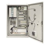
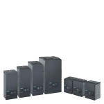
SIMOREG DC-MASTER 6RM70 Digital converter cabinet units
SIMOREG DC-MASTER 6RM70 Digital converter cabinet units Overview Ordering guidelines Standard cabinet Observe the following points when ordering a cabinet without options: Every standard cabinet has a setpoint potentiometer fitted in the door as well as a switch with which the setpoint input can be selected between this potentiometer and another input. An outgoing circuit with a motor circuit breaker is provided for each of the fan motors of the DC motor, as listed on pages 31 and 32. In the case of fan motors with a voltage other than 400 V, it is essential to specify the fan voltage (option Y01), otherwise 400 V will be assumed as standard. When using cabinet units with a mains voltage greater than 415 V, a control voltage of 3-ph. 400 V must be provided for excitation, motor fan and internal cabinet control. The current rating required for this supply is listed on pages 18 and 19 for the various types. When using cabinets for voltages up to and including 415 V, this voltage is derived from the mains supply. In addition to the switching devices for setpoint input, the door also includes an E-STOP button and the OP1S control panel for parameterization and local control of the converter. Furthermore, the door includes a switch for the control voltage in the case of units of 1500 A and above, or those with mains voltages greater than 415 V. The “E-STOP” button fitted as standard is not an EMERGENCY OFF function. Only the supply (armature and field) is disconnected from the mains, and the drive coasts. The control voltage circuit is still live. The converter unit has 4 digital inputs with relay couplers which are designed as standard by the customer with a 230 V coil (specify option C51 for 24 V coil). Please note with standard cabinets that it is assumed that the mains voltage is the same as the rated unit voltage, i.e. 400 V, 460 V, 500 V, 690 V, 830 V. Please specify other mains voltages and frequencies using option V48. Ordering Always pass on as much information as possible when ordering cabinet units 6RM70. When ordering cabinets for mains voltages greater than 400 V, and if a 3-ph. 400 V control voltage is not available, it is advantageous to know all data of the outgoing circuits to be supplied (field, motor fan). The matching transformers can then be designed according to the drive. The following data are generally important: Contact partner for any queries. Motor data (armature, field, cooling, pick-up) or, if a Siemens motor is used, its Order No. including all options. Power/current/voltage of the fan motor or, if none is present (external ventilation using pipe system), option W15. Specify different degrees of protection or regulations together with the order. If available, specify duty cycle. Notes An additional cabinet may be necessary when combining certain options, e.g. A45 “Overvoltage protection”, W10 “Radio interference suppression filter”, mains voltage greater than 400 V without the availability of a 400 V control voltage supply with relatively large control voltage transformers. The set values for the motor circuit breakers must be checked during commissioning. The scope of delivery includes the hardware, but not parameterization and commissioning. With a mains voltage less than or equal to 415 V/50 Hz, the motor fan and the internal cabinet supplies are derived from the primary current path and also supplied with this voltage. With mains voltages greater than 415 V/50 Hz, an external supply provided by the customer is expected for the motor fan and auxiliaries. This must be 3-ph. 400 V. When specifying the option V60 (60-Hz frequency), the control voltage provided by the customer must be 3-ph. 460 V/60 Hz. Application SIMOREG converter cabinet units are tested drive converter units, which are ready to connect-up to supply variable-speed DC motors. All of the open-loop and closed-loop control functions as well as the monitoring- and auxiliary functions are handled by two microprocessors in the SIMOREG. The cabinet units include all of the components which are required to operate a variable-speed DC motor. The cabinet units can be directly connected to 3-phase line supplies with rated voltages of 3-ph. 400 V AC, 500 V, 690 V, 830 V AC, 50 Hz. Other supply voltages between 3-ph. 90 V AC and 830 V AC, 50 Hz as well as 60 Hz line frequencies, refer to the options. Cabinet units are available for: Single-quadrant operation with a fully-controlled six-pulse bridge circuit B6C (rated DC currents 30 A to 2000 A) Four-quadrant operation with an antiparallel circuit with two fully-controlled six-pulse bridge circuits (B6)A(B6)C (rated DC currents 15 A to 2000 A). Special versions for parallel connection, 12-pulse operation and field supply on request. Design The cabinet units contain the following components: SIMOREG DC-MASTER 6RA70 drive converters with microprocessor-based digital closed-loop control for the armature- and field circuits Main switch (=D3-Q11) Main contactor (=D3-K11) Field contactor (=G1-K11) Circuit-breaker Motor protection circuit breaker Fuses Commutating reactors Control voltage transformers Display- and operator control elements Terminals. The components are mounted in a cabinet, and are ready to be connected-up (cabinet system: Rittal TS8). All of the components are accessible from the front of the cabinet, i.e. the cabinet units can be mounted with their rear panels to walls. For units up to 60 A, the main switch is mounted on the side.
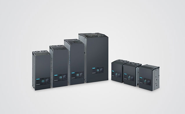
SINAMICS DCM
SINAMICS DCM Overview SINAMICS DC MASTER is the new generation of DC converters from Siemens. The name SINAMICS DC MASTER – briefly: SINAMICS DCM – embodies the strengths of this new generation. It combines the advantages of its predecessor SIMOREG DC-MASTER, with the advantages of the SINAMICS family. When it comes to quality, reliability and functionality, SINAMICS DC MASTER is not only on par with its predecessor – but especially in the area of functionality – offers new features and includes useful functions from its predecessor as standard. SINAMICS DC MASTER is the new member of the SINAMICS family that now makes many of the SINAMICS tools and components known from AC technology available to DC technology. As a scalable drive system, the SINAMICS DC MASTER series of converters is convincing both for basic as well as demanding applications. The DC Converter is equipped with a Standard Control Unit (Standard CUD). The option of combining a Standard CUD and Advanced CUD is used to address applications demanding a higher computational performance and more interfaces. The DC Converter of the SINAMICS DC MASTER series combines the open-loop and closed-loop control and power sections in one device. It especially sets itself apart as a result of the compact, space-saving design. The AOP30 Advanced Operator Panel and the BOP20 Basic Operator Panel can be used for commissioning and local operation. The interfaces of the CUD and the number of digital inputs and outputs can be supplemented using additional modules – such as the TM15, TM31 and TM150 Terminal Modules. The components of a DC drive system and how these are logically interlinked are shown in the diagram under “The system components of a DC drive” – “Overview”. A flow diagram is provided in the same section under “Engineering” to provide support when selecting and dimensioning the required components.
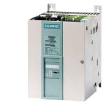
SIMOREG DC-MASTER 6RA70 Digital Chassis Converters
SIMOREG DC-MASTER 6RA70 Digital Chassis Converters Overview Power section and cooling SIMOREG 6RA70 converters are fully digital, compact units for connection to a three-phase AC supply. They in turn supply the armature and field of variable-speed DC drives. The range of rated DC currents extends from 15 A to 3000 A, but can be expanded by connecting SIMOREG converters in parallel. Converters for single-quadrant or four quadrant operation are available to suit individual applications. As the converters feature an integrated parameterization panel, they are autonomous and do not require any additional parameterization equipment. All open-loop and closed-loop control tasks as well as monitoring and auxiliary functions are performed by a microprocessor system. Setpoints and actual values can be applied in either analog or digital form. SIMOREG 6RA70 converters are characterized by their compact, space-saving design. An electronics box containing the closed-loop control board is mounted in the converter door. This box also has space to hold additional boards for process-related expansion functions and serial interfaces. This design makes them especially easy to service since individual components are easily accessible. External signals (binary inputs/output), analog inputs/outputs, pulse encoders, etc.) are connected by way of plug-in terminals. The converter software is stored in a flash EPROM. Software upgrades can easily be loaded via the serial interface of the basic unit. Power section: Armature and field circuit The armature circuit is a three-phase bridge connection: As a fully controlled B6C three-phase connection in converters for single-quadrant drives As two fully controlled (B6) A (B6) C three-phase connections in converters for four-quadrant drives. The field circuit is a half-controlled B2HZ single-phase bridge connection. For converters with 15 to 1200 A rated DC current, the power section for armature and field is constructed with isolated thyristor modules. The heat sink is therefore at floating potential. For converters with rated currents ≥ 1500 A, the power section for armature and field is constructed with disc-type thyristors and heat sinks at voltage potential. All connecting terminals for the power section are accessible from the front. Cooling Converters with rated DC currents up to 125 A are self-cooled, while converters with rated DC currents of 210 A and higher have forced-air cooling (fan assembly). Parameterization devices PMU simple operator panel All units feature a PMU panel mounted in the converter door. The PMU consists of a five-digit, seven-segment display, three LEDs as status indicators and three parameterization keys. The PMU is also equipped with connector X300 with a USS interface in compliance with the RS232 or RS485 standard. The panel provides all the facilities required during start-up for making adjustments or settings and displaying measured values. The following functions are assigned to the three panel keys: P (select) key Switches over between parameter number and parameter value and vice versa, ack-nowledges fault messages. UP key Selects a higher parameter number in parameter mode or raises the set and displayed parameter value in value mode. Also selects a higher index on indexed parameters. DOWN key Selects a lower parameter number in parameter mode or reduces the set and displayed parameter value in value mode. Also selects a lower index on indexed parameters. LED functions Ready: Ready to operate, lights up in the “Wait for operation enable” state. Run: In operation, lights up when operation is enabled. Fault: Disturbance, lights up in “Active fault” status, flashes when alarm is active. The quantities output on the five-digit, seven-segment display are easy to understand, e.g.. Percentage of rated value Servo gain factor Seconds Amperes or Volts OP1S converter operator panel The OP1S optional converter operator panel can be mounted either in the converter door or externally, e.g. in the cubicle door. For this purpose, it can be connected up by means of a 5 m long cable. Cables of up to 200 m in length can be used if a separate 5 V supply is available. The OP1S is connected to the SIMOREG via connector X300. The OP1S can be installed as an economic alternative to control cubicle measuring instruments which display physical measured quantities. The OP1S features an LCD with 4 x 16 characters for displaying parameter names in plain text. English, German, French, Spanish and Italian can be selected as the display languages. The OP1S can store parameter sets for easy downloading to other devices. Keys on OP1S: Select key (P) UP key 1) DOWN key Reversing key 1) ON key 1) OFF key 1) Inching key (Jog) 1) Numeric keys (0 to 9) LEDs on OP1S: Green: Lights up in “Run”, flashes in “Ready” Red: Lights up with “Fault”, flashes with “Alarm” RESET key 1) Parameterization devices Parameterization via PC To allow start-up and troubleshooting using a PC, the DriveMonitor software is supplied with the converters. The PC is linked to the SIMOREG via the USS interface on the basic unit. The software provides the following functions: Menu-assisted access to parameters. Reading and writing of parameter sets. Copying of existing parameter sets to other converters of the same type. Output of parameter sets to a printer. Operation via control words (binary commands such as ON/OFF instructions, etc.) and specification of setpoints. Monitoring via status words (checkback information about converter status) and readout of actual values. Reading of fault messages and alarms. Readout of trace buffer contents (oscilloscope function) 1) This function must be activated with parameters and is freely selectable.