MicroMaster

MicroMaster
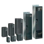
MICROMASTER 440
MICROMASTER 440 Overview Application The MICROMASTER 440 inverter is suitable for a variety of variable-speed drive applications. Its flexibility provides for a wide spectrum of applications. These also include cranes and hoisting gear, high-bay warehouses, production machines for food, beverages and tobacco, packaging machines etc.; i.e. applications which require the frequency inverter to have a higher functionality and dynamic response than usual. The inverter is especially characterized by its customer-oriented performance and ease-of-use. Its large mains voltage range enables it to be used all over the world. Design The MICROMASTER 440 has a modular design. The operator panels and the modules can be easiliy exchanged. International standards The MICROMASTER 440 inverter complies with the requirements of the EU low-voltage guideline. The MICROMASTER 440 inverter has the CE marking. Acc. to UL and c UL certified c-tick Main characteristics Easy, guided start-up Modular construction allows maximum configuration flexibility Six programmable isolated digital inputs Two scaleable analog inputs (0 V to 10 V, 0 mA to 20 mA) can also be used as a 7th/8th digital input Two programmable analog outputs (0 mA to 20 mA) Three programmable relay outputs (30 V DC/5 A, resistive load; 250 V AC/2 A, inductive load) Low-noise motor operation thanks to high pulse frequencies, adjustable (observe derating if necessary) Protection for motor and inverter Options (overview) EMC filter, Class A/B LC filter and sinusoidal filter Line commutating chokes Output chokes Gland plates Basic Operator Panel (BOP) for parameterizing the inverter Plain text Advanced Operator Panel (AOP) with multilanguage display Plain text Asian Advanced Operator Panel (AAOP) with Chinese and English display Plain text Cyrillic Advanced Operator Panel (CAOP) with Cyrillic, German and English display Communication modules PROFIBUS DeviceNet CANopen Pulse encoder evaluation module PC connection kits Mounting kits for installing the operator panels in the control cabinet doors PC start-up tools, executable under Windows 98/NT/2000/XP Professional TIA integration with Drive ES Mechanical features Modular design Operating temperature 0.12 kW to 75 kW: -10 °C to +50 °C (+14 °F to +122 °F) 90 kW to 200 kW: 0 °C to +40 °C (+32 °F to +104 °F) Compact housing as a result of high power density Easy cable connection, mains and motor connections are separated for optimum electromagnetic compatibility Detachable operator panels Screwless control terminals on detachable I/O board Performance features Latest IGBT technology Digital microprocessor control High-quality Vector Control system Flux Current Control (FCC) for improved dynamic response and optimized motor control Linear V/f characteristic Quadratic V/f characteristic Multipoint characteristic (programmable V/f characteristic) Torque control Flying restart Slip compensation Automatic restart following mains failure or fault User-definable function blocks for logic and arithmetic operations Kinetic buffering Positioning ramp down High-grade PID controller for simple internal process control (autotuning) Programmable acceleration/deceleration, 0 s to 650 s Ramp smoothing Fast Current Limit (FCL) for trip-free operation Fast, repeatable digital input response time Fine adjustment using two high-resolution 10-bit analog inputs Compound braking for controlled rapid braking Integrated brake chopper (only for 0.12 kW to 75 kW inverters) Four skip frequencies Removable “Y” capacitor for use on IT mains supplies (with non-grounded mains supplies, the “Y” capacitor must be removed, and an output choke installed) Protection features Overload capability CT mode 0.12 kW to 75 kW: Overload current 1.5 x rated output current (i.e. 150 % overload capability) for 60 s, cycle time 300 s, and 2 x rated output current (i.e. 200 % overload capability) for 3 s, cycle time 300 s 90 kW to 200 kW: Overload current 1.36 x rated output current (i.e. 136 % overload capability) for 57 s, cycle time 300 s, and 1.6 x rated output current (i.e. 160 % overload capability) for 3 s, cycle time 300 s VT mode 5.5 kW to 90 kW: Overload current 1.4 x rated output current (i.e. 140 % overload capability) for 3 s, and 1.1 x rated output current (i.e. 110 % overload capability) for 60 s, cycle time 300 s 110 kW to 250 kW: Overload current 1.5 x rated output current (i.e. 150 % overload capability) for 1 s, and 1.1 x rated output current (i.e. 110 % overload capability) for 59 s, cycle time 300 s Overvoltage/undervoltage protection Inverter overtemperature protection Special direct connection for PTC or KTY to protect the motor Earth fault protection Short-circuit protection I2t motor thermal protection Locked motor protection Stall prevention Parameter interlock
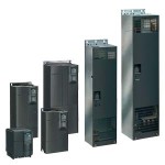
MICROMASTER 430
MICROMASTER 430 Overview Application The MICROMASTER 430 inverter is suitable for a variety of variable-speed drive applications. Its flexibility provides for a wide spectrum of applications. It is especially suitable for use with industrial pumps and fans. The inverter is especially characterized by its customer-oriented performance and ease-of-use. It has more inputs and outputs than the MICROMASTER 420, an optimized operator panel with manual/automatic switchover, and adapted software functionality. Design The MICROMASTER 430 inverter has a modular design. The operator panels and communication modules can be easily exchanged. Main characteristics Easy, guided start-up Modular construction allows maximum configuration flexibility Six programmable isolated digital inputs Two scaleable analog inputs (0 V to 10 V, 0 mA to 20 mA) can also be used as a 7th/8th digital input Two programmable analog outputs (0 mA to 20 mA) Three programmable relay outputs 30 V DC/5 A, resistive load 250 V AC/2 A, inductive load Low-noise motor operation thanks to high pulse frequencies, adjustable (observe derating if necessary) Protection for motor and inverter Control of up to three additional drives on the basis of PID control (motor staging) Operation of drive directly on mains (with external bypass circuit) Low-energy mode Detects dry run of pumps (belt failure detection) Options (overview) Line commutating chokes Output chokes LC filter and sinusoidal filter Gland plates Basic Operator Panel 2 (BOP-2) for parameterizing the inverter Communication modules PROFIBUS DeviceNet CANopen PC connection kits Mounting kits for installing the operator panels in the control cabinet doors PC start-up tools, executable under Windows 98/NT/2000/ME/XP Professional TIA integration with Drive ES International standards The MICROMASTER 430 inverter complies with the requirements of the EU low-voltage guideline. The MICROMASTER 430 inverter has CE marking. Acc. to UL and c UL certified c-tick Mechanical features Modular design Operating temperature: –10 °C to +40 °C (+14 °F to +104 °F) Compact housing as a result of high power density Easy cable connection, mains and motor connections are separated for optimum electromagnetic compatibility Detachable operator panels Screwless control terminals on detachable I/O board Performance features Latest IGBT technology Digital microprocessor control Flux Current Control (FCC) for improved dynamic response and optimized motor control Linear V/f characteristic Quadratic V/f characteristic Multipoint characteristic (programmable V/f characteristic) Flying restart Slip compensation Automatic restart facility following power failure or fault Energy saving mode (stopping e.g. of a pump at low speeds) Motor staging (connection and disconnection of additional motors, use of inverter as control drive in a pump cascade) Manual/automatic mode Load torque monitoring (belt failure detection; detects dry run of pumps) High-grade internal PID controller for simple process control Programmable acceleration/deceleration times, 0 s to 650 s Ramp smoothing Fast Current Limit (FCL) for trip-free operation Fast, repeatable digital input response time Fine adjustment using two high-resolution 10-bit analog inputs Compound braking for rapid controlled braking Four skip frequencies Removable “Y” capacitor for use on IT systems (with non-grounded mains supplies, the “Y” capacitor must be removed, and an output choke installed) Protection features Overload capability 7.5 kW to 90 kW: Overload current 1.4 x rated output current (i.e. 140 % overload capability) for 3 s and 1.1 x rated output current (i.e. 110 % overload capability) for 60 s, cycle time 300 s 110 kW to 250 kW: Overload current 1.5 x rated output current (i.e. 150 % overload capability) for 1 s and 1.1 x rated output current (i.e. 110 % overload capability) for 59 s, cycle time 300 s Overvoltage/undervoltage protection Inverter overtemperature protection Special direct connection for PTC or KTY to protect the motor Earth fault protection Short-circuit protection I2t motor thermal protection Locked motor protection Stall prevention Parameter interlock
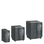
MICROMASTER 420
MICROMASTER 420 Overview Application The MICROMASTER 420 inverter is suitable for a variety of variable-speed drive applications. It is especially suitable for applications for pumps, fans and conveyor systems. It is the ideal cost-optimized frequency inverter solution. The inverter is especially characterized by its customer-oriented performance and ease-of-use. Its large supply-voltage range enables it to be used all over the world. Design The MICROMASTER 420 has a modular design. The operator panels and communication modules can be easily exchanged without requiring any tools. Main characteristics Easy, guided start-up Modular construction allows maximum configuration flexibility Three fully programmable isolated digital inputs One scalable analog input (0 V to 10 V) can also be used as a 4th digital input One programmable analog output (0 mA to 20 mA) One programmable relay output 30 V DC/5 A, resistive load 250 V AC/2 A, inductive load Low-noise motor operation through high pulse frequency, adjustable (observe derating if necessary) Complete inverter and motor protection Options (overview) EMC filter, Class A/B LC filter Line commutating chokes Output chokes Gland plates Basic Operator Panel (BOP) for parameterizing the inverter Advanced Operator Panel (AOP) with multi-language plain text display Asian Advanced Operator Panel (AAOP) with Chinese and English plain text display Cyrillic Advanced Operator Panel (CAOP) with Cyrillic, German and English plain text display Communication modules PROFIBUS DeviceNet CANopen PC connection sets Mounting kits for installing the operator panels in the control cabinet doors PC start-up programs executable under Windows 98/NT/2000/XP Professional TIA integration with Drive ES International standards The MICROMASTER 420 inverter complies with the requirements of the EU low-voltage guideline. The MICROMASTER 420 inverter has the CE marking. Acc. to uL and cuL certified c-tick Mechanical features Modular design Operating temperature: -10 °C to +50 °C (+14 °F to +122 °F) Compact housing as a result of high power density Easy cable connection, mains and motor connections are separated for optimum electromagnetic compatibility Detachable operator panels Screwless control terminals Performance features Latest IGBT technology Digital microprocessor control Flux current control (FCC) for improved dynamic response and optimized motor control Linear V/f characteristic Quadratic V/f characteristic Multipoint characteristic (programmable V/f characteristic) Flying restart Slip compensation Automatic restart facility following mains failure or fault Internal PI controller for simple process control Programmable acceleration/deceleration, 0 s to 650 s Ramp smoothing Fast current limit (FCL) for trip-free operation Fast, repeatable digital input response time Fine adjustment using a high resolution 10-bit analog input Compound braking for rapid controlled braking Four skip frequencies Removable “Y” capacitor for use on IT systems (with non-grounded mains supplies, the “Y” capacitor must be removed and an output choke installed) Protection features Overload current 1.5 x rated output current (i.e. 150 % overload capability) for 60 s, cycle time 300 s Overvoltage/undervoltage protection Inverter overtemperature protection Motor protection using PTC via digital input (possible with supplementary circuit) Earth fault protection Short-circuit protection I2t motor thermal protection Locked motor protection Stall prevention Parameter interlock