- GIẢI PHÁP SẠC XE Ô TÔ ĐIỆN NVCharge
- DANFOSS
- NĂNG LƯỢNG TÁI TẠO
- GIẢI PHÁP TÍCH HỢP
- Hệ thống biến tần trung, hạ áp
- Hệ thống cân băng tải
- Hệ thống chuyển nguồn điện tự động ATS
- Hệ thống điều khiển động cơ MCC
- Hệ thống điều khiển phân tán DCS
- Hệ thống điều khiển PLC - Scada
- Hệ thống điều khiển TPS
- Hệ thống giám sát và nhiệt trị than online
- Hệ thống khởi động mềm trung, hạ áp
- Hệ thống UPS
- Tủ điện phân phối MDB & DB, tủ cấp nguồn
- MARECHAL - TECHNOR
- BORRI
- FLENDER
- DURAG
- SOLCON
- SIEMENS
- METSO OUTOTEC
- DỊCH VỤ KỸ THUẬT
Liên hệ
CÔNG TY CỔ PHẦN THƯƠNG MẠI KỸ THUẬT HẢI ANH – HAI ANH JSC
Trụ sở tại TP Hà Nội:
+ Địa chỉ: P301, Nhà D5C, đường Trần Thái Tông, phường Cầu Giấy, TP. Hà Nội, Việt Nam
+ ĐT: (+84-24) 6269 7755
+ Fax: (+84-24) 6269 5556Trung tâm nghiên cứu, sản xuất công nghệ cao Nova Energy:
Lô đất CN1-12B – 1.3, Khu công nghiệp công nghệ cao 1, Khu Công nghệ cao Hòa Lạc, xã Hạ Bằng, Hà Nội, Việt Nam
+ ĐT: (+84-24) 3202 2677Chi nhánh tại miền Trung:
+ Địa chỉ: P1109, Toà A, chung cư Tecco Đông vệ, phường Hạc Thành, tỉnh Thanh Hoá, Việt Nam
+ ĐT: (+84-23) 7383 8886Chi nhánh tại miền Nam:
+ Địa chỉ: Tầng 1, Tòa nhà Gia Thy, 158 Đào Duy Anh, phường Đức Nhuận, Thành phố Hồ Chí Minh, Việt Nam
+ ĐT: (+84-28) 3517 8949
+ Fax: (+84-28) 3517 8950-

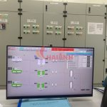
Hệ thống đo lường mạng ngoài – dự án Hòa Phát Dung Quất 2
-

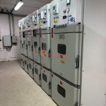
Hệ thống tủ điện trung thế tại Xi măng Hoàng Mai
-

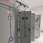
Hệ thống điện và điều khiển nhà máy HPS2 Phong Điền
-

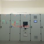
Hệ thống điện trạm khí nén – Nhiệt điện Hòa Phát Dung Quất 1
-

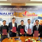
Hải Anh JSC và VINALIFT ký kết hợp tác chiến lược cùng các đối tác công nghệ toàn cầu: Siemens, Innomotics, Flender
Danh mục sản phẩm
Tin tức mới
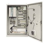
SIMOREG DC-MASTER 6RM70 Digital converter cabinet units
SIMOREG DC-MASTER 6RM70 Digital converter cabinet units Overview Ordering guidelines Standard cabinet Observe the following points when ordering a cabinet without options: Every standard cabinet has a setpoint potentiometer fitted in the door as well as a switch with which the setpoint input can be selected between this potentiometer and another input. An outgoing circuit with a motor circuit breaker is provided for each of the fan motors of the DC motor, as listed on pages 31 and 32. In the case of fan motors with a voltage other than 400 V, it is essential to specify the fan voltage (option Y01), otherwise 400 V will be assumed as standard. When using cabinet units with a mains voltage greater than 415 V, a control voltage of 3-ph. 400 V must be provided for excitation, motor fan and internal cabinet control. The current rating required for this supply is listed on pages 18 and 19 for the various types. When using cabinets for voltages up to and including 415 V, this voltage is derived from the mains supply. In addition to the switching devices for setpoint input, the door also includes an E-STOP button and the OP1S control panel for parameterization and local control of the converter. Furthermore, the door includes a switch for the control voltage in the case of units of 1500 A and above, or those with mains voltages greater than 415 V. The “E-STOP” button fitted as standard is not an EMERGENCY OFF function. Only the supply (armature and field) is disconnected from the mains, and the drive coasts. The control voltage circuit is still live. The converter unit has 4 digital inputs with relay couplers which are designed as standard by the customer with a 230 V coil (specify option C51 for 24 V coil). Please note with standard cabinets that it is assumed that the mains voltage is the same as the rated unit voltage, i.e. 400 V, 460 V, 500 V, 690 V, 830 V. Please specify other mains voltages and frequencies using option V48. Ordering Always pass on as much information as possible when ordering cabinet units 6RM70. When ordering cabinets for mains voltages greater than 400 V, and if a 3-ph. 400 V control voltage is not available, it is advantageous to know all data of the outgoing circuits to be supplied (field, motor fan). The matching transformers can then be designed according to the drive. The following data are generally important: Contact partner for any queries. Motor data (armature, field, cooling, pick-up) or, if a Siemens motor is used, its Order No. including all options. Power/current/voltage of the fan motor or, if none is present (external ventilation using pipe system), option W15. Specify different degrees of protection or regulations together with the order. If available, specify duty cycle. Notes An additional cabinet may be necessary when combining certain options, e.g. A45 “Overvoltage protection”, W10 “Radio interference suppression filter”, mains voltage greater than 400 V without the availability of a 400 V control voltage supply with relatively large control voltage transformers. The set values for the motor circuit breakers must be checked during commissioning. The scope of delivery includes the hardware, but not parameterization and commissioning. With a mains voltage less than or equal to 415 V/50 Hz, the motor fan and the internal cabinet supplies are derived from the primary current path and also supplied with this voltage. With mains voltages greater than 415 V/50 Hz, an external supply provided by the customer is expected for the motor fan and auxiliaries. This must be 3-ph. 400 V. When specifying the option V60 (60-Hz frequency), the control voltage provided by the customer must be 3-ph. 460 V/60 Hz. Application SIMOREG converter cabinet units are tested drive converter units, which are ready to connect-up to supply variable-speed DC motors. All of the open-loop and closed-loop control functions as well as the monitoring- and auxiliary functions are handled by two microprocessors in the SIMOREG. The cabinet units include all of the components which are required to operate a variable-speed DC motor. The cabinet units can be directly connected to 3-phase line supplies with rated voltages of 3-ph. 400 V AC, 500 V, 690 V, 830 V AC, 50 Hz. Other supply voltages between 3-ph. 90 V AC and 830 V AC, 50 Hz as well as 60 Hz line frequencies, refer to the options. Cabinet units are available for: Single-quadrant operation with a fully-controlled six-pulse bridge circuit B6C (rated DC currents 30 A to 2000 A) Four-quadrant operation with an antiparallel circuit with two fully-controlled six-pulse bridge circuits (B6)A(B6)C (rated DC currents 15 A to 2000 A). Special versions for parallel connection, 12-pulse operation and field supply on request. Design The cabinet units contain the following components: SIMOREG DC-MASTER 6RA70 drive converters with microprocessor-based digital closed-loop control for the armature- and field circuits Main switch (=D3-Q11) Main contactor (=D3-K11) Field contactor (=G1-K11) Circuit-breaker Motor protection circuit breaker Fuses Commutating reactors Control voltage transformers Display- and operator control elements Terminals. The components are mounted in a cabinet, and are ready to be connected-up (cabinet system: Rittal TS8). All of the components are accessible from the front of the cabinet, i.e. the cabinet units can be mounted with their rear panels to walls. For units up to 60 A, the main switch is mounted on the side.
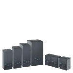
SINAMICS DCM
SINAMICS DCM Overview SINAMICS DC MASTER is the new generation of DC converters from Siemens. The name SINAMICS DC MASTER – briefly: SINAMICS DCM – embodies the strengths of this new generation. It combines the advantages of its predecessor SIMOREG DC-MASTER, with the advantages of the SINAMICS family. When it comes to quality, reliability and functionality, SINAMICS DC MASTER is not only on par with its predecessor – but especially in the area of functionality – offers new features and includes useful functions from its predecessor as standard. SINAMICS DC MASTER is the new member of the SINAMICS family that now makes many of the SINAMICS tools and components known from AC technology available to DC technology. As a scalable drive system, the SINAMICS DC MASTER series of converters is convincing both for basic as well as demanding applications. The DC Converter is equipped with a Standard Control Unit (Standard CUD). The option of combining a Standard CUD and Advanced CUD is used to address applications demanding a higher computational performance and more interfaces. The DC Converter of the SINAMICS DC MASTER series combines the open-loop and closed-loop control and power sections in one device. It especially sets itself apart as a result of the compact, space-saving design. The AOP30 Advanced Operator Panel and the BOP20 Basic Operator Panel can be used for commissioning and local operation. The interfaces of the CUD and the number of digital inputs and outputs can be supplemented using additional modules – such as the TM15, TM31 and TM150 Terminal Modules. The components of a DC drive system and how these are logically interlinked are shown in the diagram under “The system components of a DC drive” – “Overview”. A flow diagram is provided in the same section under “Engineering” to provide support when selecting and dimensioning the required components.
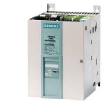
SIMOREG DC-MASTER 6RA70 Digital Chassis Converters
SIMOREG DC-MASTER 6RA70 Digital Chassis Converters Overview Power section and cooling SIMOREG 6RA70 converters are fully digital, compact units for connection to a three-phase AC supply. They in turn supply the armature and field of variable-speed DC drives. The range of rated DC currents extends from 15 A to 3000 A, but can be expanded by connecting SIMOREG converters in parallel. Converters for single-quadrant or four quadrant operation are available to suit individual applications. As the converters feature an integrated parameterization panel, they are autonomous and do not require any additional parameterization equipment. All open-loop and closed-loop control tasks as well as monitoring and auxiliary functions are performed by a microprocessor system. Setpoints and actual values can be applied in either analog or digital form. SIMOREG 6RA70 converters are characterized by their compact, space-saving design. An electronics box containing the closed-loop control board is mounted in the converter door. This box also has space to hold additional boards for process-related expansion functions and serial interfaces. This design makes them especially easy to service since individual components are easily accessible. External signals (binary inputs/output), analog inputs/outputs, pulse encoders, etc.) are connected by way of plug-in terminals. The converter software is stored in a flash EPROM. Software upgrades can easily be loaded via the serial interface of the basic unit. Power section: Armature and field circuit The armature circuit is a three-phase bridge connection: As a fully controlled B6C three-phase connection in converters for single-quadrant drives As two fully controlled (B6) A (B6) C three-phase connections in converters for four-quadrant drives. The field circuit is a half-controlled B2HZ single-phase bridge connection. For converters with 15 to 1200 A rated DC current, the power section for armature and field is constructed with isolated thyristor modules. The heat sink is therefore at floating potential. For converters with rated currents ≥ 1500 A, the power section for armature and field is constructed with disc-type thyristors and heat sinks at voltage potential. All connecting terminals for the power section are accessible from the front. Cooling Converters with rated DC currents up to 125 A are self-cooled, while converters with rated DC currents of 210 A and higher have forced-air cooling (fan assembly). Parameterization devices PMU simple operator panel All units feature a PMU panel mounted in the converter door. The PMU consists of a five-digit, seven-segment display, three LEDs as status indicators and three parameterization keys. The PMU is also equipped with connector X300 with a USS interface in compliance with the RS232 or RS485 standard. The panel provides all the facilities required during start-up for making adjustments or settings and displaying measured values. The following functions are assigned to the three panel keys: P (select) key Switches over between parameter number and parameter value and vice versa, ack-nowledges fault messages. UP key Selects a higher parameter number in parameter mode or raises the set and displayed parameter value in value mode. Also selects a higher index on indexed parameters. DOWN key Selects a lower parameter number in parameter mode or reduces the set and displayed parameter value in value mode. Also selects a lower index on indexed parameters. LED functions Ready: Ready to operate, lights up in the “Wait for operation enable” state. Run: In operation, lights up when operation is enabled. Fault: Disturbance, lights up in “Active fault” status, flashes when alarm is active. The quantities output on the five-digit, seven-segment display are easy to understand, e.g.. Percentage of rated value Servo gain factor Seconds Amperes or Volts OP1S converter operator panel The OP1S optional converter operator panel can be mounted either in the converter door or externally, e.g. in the cubicle door. For this purpose, it can be connected up by means of a 5 m long cable. Cables of up to 200 m in length can be used if a separate 5 V supply is available. The OP1S is connected to the SIMOREG via connector X300. The OP1S can be installed as an economic alternative to control cubicle measuring instruments which display physical measured quantities. The OP1S features an LCD with 4 x 16 characters for displaying parameter names in plain text. English, German, French, Spanish and Italian can be selected as the display languages. The OP1S can store parameter sets for easy downloading to other devices. Keys on OP1S: Select key (P) UP key 1) DOWN key Reversing key 1) ON key 1) OFF key 1) Inching key (Jog) 1) Numeric keys (0 to 9) LEDs on OP1S: Green: Lights up in “Run”, flashes in “Ready” Red: Lights up with “Fault”, flashes with “Alarm” RESET key 1) Parameterization devices Parameterization via PC To allow start-up and troubleshooting using a PC, the DriveMonitor software is supplied with the converters. The PC is linked to the SIMOREG via the USS interface on the basic unit. The software provides the following functions: Menu-assisted access to parameters. Reading and writing of parameter sets. Copying of existing parameter sets to other converters of the same type. Output of parameter sets to a printer. Operation via control words (binary commands such as ON/OFF instructions, etc.) and specification of setpoints. Monitoring via status words (checkback information about converter status) and readout of actual values. Reading of fault messages and alarms. Readout of trace buffer contents (oscilloscope function) 1) This function must be activated with parameters and is freely selectable.
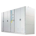
SINAMICS SM150
SINAMICS SM150 Overview SINAMICS SM150 The sophisticated drive solution for single and multi-motor drives in the medium voltage General description The decades of experience that we have gained with our SIMOVERT ML, SIMOVERT ML2, drive converters, transrapid line feeder systems and traction power supply links culminate and merge in the SINAMICS SM150. SINAMICS SM150 is a high‑end drive converter for low and high speed applications. This is the reason that it is recommended for applications requiring a high dynamic performance and regenerative feedback into the line supply – generally with special motors from approx. 2.8 ‑ 30.6 MW. The water‑cooled SINAMICS SM150 drive converters, capable of regenerative feedback into the line supply, are available as either single‑motor or multi‑motor drive with well‑proven IGCT power semiconductors for medium‑voltage drive applications. For the multi-motor drives, a common DC bus allows direct energy exchange for applications that involve both motoring and generating drives. In the low power range well‑proven IGBT power semiconductors are used for single‑motor application as air cooled drive configuration. Benefits Easy plant integration due to the compact design and highly flexible configuration Simple operator control with the user‑friendly operator panel Smooth and reliable operation due to the integrated maintenance functions: the converter signals automatically and well in advance when maintenance is required and/or components need to be exchanged High ruggedness and reliability thanks to the use of IGCT/HV‑IGBT technology and fuseless design, combined with intelligent response to external disturbances Hassle‑free integration into higher-level automation systems due to PROFIBUS interface supplied as standard and analog and digital interfaces High degree of service‑friendliness due to the innovative power section design, e.g. compact phase modules and excellent accessibility of all components only applicable to the IGCT technology Ideal for direct energy exchange on the common DC bus in applications with motoring and generating drives Application Moving: Belt conveyors, ship’s drives, test stands Processing: Rolling mill drives Further, the power section is also used in Transrapid and traction power supply links. The non‑regenerative version SINAMICS GM150 (IGCT version) is available for ship’s drives, gas compressors and ore crushers.
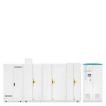
SINAMICS SM120 Cabinet Modules
SINAMICS SM120 Cabinet Modules Overview SINAMICS SM120 Cabinet Modules Superior Performance for Industrial Power Regeneration General description The SINAMICS SM120 CM (Cabinet Modules) with its multi‑level Active Line Module is uniquely suitable for industrial power regeneration applications and ensures a superior performance while feeding energy into the grid. The SINAMICS SM120 CM is the best choice to fulfill the application specific requirements which range from the need to meet electric utility’s strict standards, to react fast in the event of line failures or to create an independent island network, since it provides line‑friendly and grid‑compliant behavior and enables island network and transformer‑less operations. Features Superior line performance Due to its integrated Siemens patented M2C topology the drive provides a sinusoidal voltage wave‑form to the grid. The harmonics remain significantly below all world‑wide commonly applied utility requirements. The SINAMICS SM120 CM complies with even the most demanding grid‑code requirements, which allows smooth and effective integration into any grid while conventional regenerating drives cause harmonic currents and thus usually call for additional line filters. This is particularly important for weak and island networks to ensure robust operation. Transformer‑less System Design Especially for ship applications (e.g. shaft generators) the SINAMICS SM120 CM provides additional key benefits. Depending on the grid and the drive input voltage, the multi‑level Active Line Module can also operate directly connected to the power supply with a line reactor only. Such a transformer‑less system design saves space and weight, reduces cabling and requires no transformer monitoring. Moreover the system efficiency increases significantly. Benefits Line-friendly Grid-compliant Island network operation Transformer‑less operation Product Information Jump to Overview Benefits Application Technical specifications Overview SINAMICS SM120 Cabinet Modules Superior Performance for Industrial Power Regeneration General description The SINAMICS SM120 CM (Cabinet Modules) with its multi‑level Active Line Module is uniquely suitable for industrial power regeneration applications and ensures a superior performance while feeding energy into the grid. The SINAMICS SM120 CM is the best choice to fulfill the application specific requirements which range from the need to meet electric utility’s strict standards, to react fast in the event of line failures or to create an independent island network, since it provides line‑friendly and grid‑compliant behavior and enables island network and transformer‑less operations. Features Superior line performance Due to its integrated Siemens patented M2C topology the drive provides a sinusoidal voltage wave‑form to the grid. The harmonics remain significantly below all world‑wide commonly applied utility requirements. The SINAMICS SM120 CM complies with even the most demanding grid‑code requirements, which allows smooth and effective integration into any grid while conventional regenerating drives cause harmonic currents and thus usually call for additional line filters. This is particularly important for weak and island networks to ensure robust operation. Transformer‑less System Design Especially for ship applications (e.g. shaft generators) the SINAMICS SM120 CM provides additional key benefits. Depending on the grid and the drive input voltage, the multi‑level Active Line Module can also operate directly connected to the power supply with a line reactor only. Such a transformer‑less system design saves space and weight, reduces cabling and requires no transformer monitoring. Moreover the system efficiency increases significantly. Single Line diagram of the SINAMICS SM120 CM with a transformer‑less system design Benefits Line-friendly Grid-compliant Island network operation Transformer‑less operation Application The Active Line Module of the SINAMICS SM120 Cabinet Module (CM) with its Modular Multilevel Converter (M2C) is ideal for applications such as: Shaft generator/boosters Generators in hydro power stations Test bench drives Ore conveyors
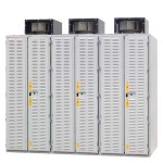
SINAMICS SL150
SINAMICS SL150 Overview SINAMICS SL150 The cycloconverter for slow-speed synchronous and induction motors with a high torque General description SINAMICS SL150 cycloconverters with thyristor stacks are the optimum choice when it comes to continuously controlling the speed of high‑rating induction and synchronous motors with a high torque and low stator frequencies. They are implemented as three‑phase thyristor bridges in a 6 or 12‑pulse connection. They set themselves apart as a result of their simple design that utilizes a relatively low number of power semiconductors. As a consequence, the SINAMICS SL150 has a high efficiency and high degree of reliability. Without any additional costs, the inherent circuit principle of the cycloconverter makes it suitable for four‑quadrant operation – i. e. driving and braking in both directions. The maximum output frequency is typically between 40 and 44 % of the line frequency. Open‑loop and closed-loop control and thyristor monitoring for the complete drive are implemented using components from the SINAMICS system. The thyristors are controlled and monitored opto-electronically via fiber‑optic cables. The heat from the power circuit is dissipated using the cabinet fans. Features High efficiency With SINAMICS SL150, low switching losses and the low loss thyristor technology ensure an extremely high efficiency (99 %). As a consequence, lower demands are placed on the cooling system. At the same time, less space is required for installation. Used worldwide The technology employed in SINAMICS SL150 has been successfully used for more than 35 years now. More than 700 units of the previous SIMOVERT D series were supplied in different versions – wherever slow speed applications demand a high power rating and the highest torque. Top marks for ruggedness and availability There are some excellent reasons why SINAMICS SL150 is extremely reliable and sets standards when it comes to ruggedness: Few components for any particular power rating: 9/18 MVA with 36 thyristors Generous and rugged design Fast fault diagnostics using an extensive, detailed message system: Trace memory for 14 signals – output at analog outputs Fault display at the operator panel Feedback diagnostics of the individual thyristors in the power unit Benefits Available with air and water cooling Four-quadrant operation High short‑time overload capability: typically 200 % for 60 seconds Can be simply integrated into the plant Simple operator control and monitoring Extremely reliable Almost maintenance‑free Can be seamlessly integrated into higher‑level automation systems Air intake either through slots in the door or from below Application Rolling mills Rolling drives that run continuously typically have 6-pole cylindrical rotor synchronous motors with a rated frequency of approx. 7 Hz (approx. 140 rpm) and a maximum frequency of approx. 20 Hz (approx. 400 rpm), while the large hot reversing stands are equipped with 12-pole motors with a frequency of approx. 5/10 Hz (approx. 50/100 rpm). Mine hoists Mine hoist drives are equipped with 12 to 16-pole synchronous motors with salient pole rotors with a rated frequency of approx. 5 to 10 Hz operating at speeds from about 50 to 90 rpm. Ore and cement crushers The 40 to 80-pole ring motors with salient pole rotors are typically operated at approx. 6 Hz (approx. 10 rpm). Excavators Technical specifications SINAMICS SL150 replaces the SIMOVERT D Thyristor‑based power unit allows power ratings of up to 36 MVA Either an open or star connection 2 × 950 6‑pulse parallel connection for high power ratings with 12‑pulse line harmonics
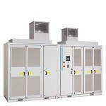
SINAMICS PERFECT HARMONY GH180
SINAMICS PERFECT HARMONY GH180 Overview SINAMICS PERFECT HARMONY GH180 The Perfect Harmony of Performance, Process and Technology General description In the SINAMICS PERFECT HARMONY GH180, a series of low‑voltage cells are linked together to build the medium‑voltage power output of the drive system. With this topology, the drive can be scaled precisely for a very wide range of voltage and output power. Additionally, the SINAMICS PERFECT HARMONY GH180 offers increased availability because of its modular design and ability to bypass any one cell during operation while maintaining the full output voltage. Furthermore, the integral transformer with phase-shifted secondaries provides 18‑pulse or better input harmonic cancellation with a power factor above 0.95 under any operating conditions. This eliminates the need for input harmonic filters or power factor compensation, while completely avoiding any common‑mode voltages from being imposed on the motor. The quality of the output voltage is so close to perfect sine-wave shape that motors of literally any type – old or new, low‑speed or high‑speed – can be operated without any additional stress. Issues related to dU/dt, overheating and increased torsion vibrations are a thing of the past. Benefits Very small footprint No output transformer required – motor voltage 2.3 to 13.8 kV can be provided directly No harmonic line filters or power factor compensation required Engineered to continue operating through component failures that would completely disable conventional drives. The patented cell-based configuration maximizes availability, letting the customer determine the right time to perform maintenance, while the modular design reduces system repair time to minutes. The cell bypass option ensures automatic bypass of a failed power cell in typically 250 ms or less (less than 1/2 of a second) through a redundant bypass control that is completely separated from each power cell. The optional process-tolerant protection system (ProToPS) in combination with cell bypass supports the high reliability and availability of the SINAMICS PERFECT HARMONY GH180. Instead of tripping the drive and automatically shutting down the system due to a malfunction, ProToPS provides a hierarchical system of warnings. This control strategy allows time to evaluate the situation and respond appropriately to avoid a system shutdown. No common mode motor insulation stress – the SINAMICS PERFECT HARMONY GH180 includes an integral isolation transformer Compatible with both new and existing 1.0 service factor induction or synchronous motors from any manufacturer without any special design considerations No significant drive-induced torque pulsations – even at low speeds No need for expensive flexible couplings No cable length restrictions Application Retrofit Power generation – SINAMICS PERFECT HARMONY GH180 can ride through voltage dips or power outages Pulp/Paper – SINAMICS PERFECT HARMONY GH180 provides high output voltage at low power
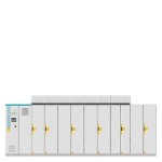
SINAMICS PERFECT HARMONY GH150
SINAMICS PERFECT HARMONY GH150 Overview General description The SINAMICS PERFECT HARMONY GH150, like its cell-based counterpart SINAMICS PERFECT HARMONY GH180, features a series of low voltage cells that are linked together to build the medium voltage power output of the drive system. With this cell-based design, the drive can be scaled precisely for a very wide range of voltage and output power. Due to its modular design and ability to bypass any cell during operation and still maintain the full output voltage, the SINAMICS PERFECT HARMONY drives offers maximum availability to an application. SINAMICS PERFECT HARMONY GH150 drives are specially designed to offer expanded versatility and easy integration. The SINAMICS PERFECT HARMONY GH150 offers some unique features like a separate transformer design, a separate control cabinet, marine certification and an arc fault tested design. Benefits Transformer Versatility: Able to utilize separate dry-type or oil-filled standard converter transformers. It is also capable of accepting transformers of different primary voltages or number of pulses. Greater Control Cabinet Flexibility: Flexible control cabinet placement enables optimization of plant layout and safety concepts with ability to install control cabinet in an alternative location or orientation to the drive. Marine and Offshore Certification: Available in marine/offshore configurations that meet the requirements of all major marine certification societies. Cell Bypass and Cell Redundancy: Maximize your process availability thanks to cell bypass and redundant cells. High-speed cell bypass feature maintains a reliable and balanced output voltage without torque or speed reduction. Extremely Motor Friendly: Capable of being configured with virtually any motor thanks to an almost sinusoidal output voltage. The motor friendliness of the drive is perfect for retrofits and long motor cable applications. Arc Fault Tested: Internal arc certification based on IEC 62271-200. Eases plant safety concepts by providing safer drive operation. Braking Chopper: This option enables to quickly stop the process or application for safety or production purposes. Application Oil & Gas and Offshore (Pumps, Fans, Compressors and ESPs) Power Generation (Pumps, Fans) Marine (Thrusters, Main Propulsion, Pumps) Metals (Fans/Blowers) Mining (Fans) Water and Wastewater (Pumps) Retrofits (Medium voltage applications, mainly pumps, fans, compressors and propulsion systems)
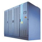
SINAMICS GM150
SINAMICS GM150 Overview SINAMICS GM150 – The universal drive solution for single drives in the medium voltage Simply straightforward – from the very start General description Our SINAMICS GM150 (IGBT/IGCT) variable speed drive brings simplicity into the medium‑voltage environment. This starts with standardized engineering using the engineering tool SIZER WEB ENGINEERING followed by the uncomplicated integration into the plant or system. This is continued with fast and user-friendly commissioning using STARTER and easy operator control. And in operation, SINAMICS GM150 distinguishes itself thanks to its ruggedness and servicefriendliness. SINAMICS GM150 is designed as a universal and simple drive converter for single‑motor applications with variable and constant torque characteristic but without regenerative feedback. SINAMICS GM150 can be optimally combined with converter motors from Siemens. In this case sine‑wave filters are not required, resulting in a very competitive, compact and efficient drive solution. With the optional sine‑wave filter the converter offers the best prerequisites for operation of standard motors and is thus optimally suited for retrofit of fixed‑speed drives to variable‑speed drives in existing installations. The SINAMICS GM150 drive converters offer an economical drive solution, which can be adapted to specific customer needs with a wide range of optionally available components and accessories. Features Reliability for every industry Oil and gas, water/waste water, power generation, mining, cement, marine, metals – a SINAMICS GM150 drive performs unaffected by environmental effects such as dust, corrosion and vibration. The control is insensitive to voltage fluctuations and electromagnetic disturbances, further increasing the overall reliability. All of this is complemented by the standardized technology of the SINAMICS family. Siemens is the first supplier on the market to already use reliable HV-IGBT power modules in the second generation! Planning and commissioning the easy way With no effort at all: Mechanical integration into the plant Front access allows wall-mounting of drive cabinets Simple and safe transport thanks to the integrated base frame Either air‑ or water‑cooled Compact design makes it easier to integrate into existing plants Space‑saving cabinet design reduces the costs of the electrical room Transformer location can be freely selected: oil‑filled transformer for outdoor installation or dry‑type for indoor installation Individual and fast: Electrical integration into the plant An extensive range of electrical options allows the drive to be flexibly adapted to specific requirements: Top or bottom cable entry All connections from the front Without filter as standard for new systems equipped with Siemens converter motors The best prerequisites for operation with motors that are designed for direct online operation, using a real sinus‑wave filter Line‑friendly using a 12‑pulse diode rectifier – or alternatively a 24‑pulse diode rectifier Benefits Easy plant integration due to the compact design and highly flexible configuration Simple operator control with the user-friendly operator panel Smooth and reliable operation due to the integrated maintenance functions: the converter signals automatically and well in advance when maintenance is required and/or components need to be exchanged High ruggedness and reliability thanks to the use of HV-IGBT/IGCT technology and fuseless design, combined with intelligent response to external disturbances Hassle-free integration into higher-level automation systems due to PROFIBUS interface supplied as standard and analog and digital interfaces High degree of service-friendliness due to the innovative power section design, e.g. plug-in powercards and excellent accessibility of all components only applicable to the HV-IGBT technology Application Moving: Belt conveyors, ship’s drives Processing: Mills, mixers, kneaders, crushers, agitators, rotary furnaces, extruders Technical specifications Power section with HV-IGBT technology for power ratings up to 13 MVA. SINAMICS GM150 (IGBT) is the successor of SIMOVERT MV. Power section with IGCT technology for ratings starting from 10 MVA up to 21 MVA (up to 24 MVA in tandem configuration)
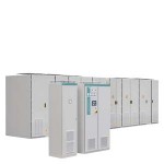
SINAMICS GL150
SINAMICS GL150 Overview SINAMICS GL150 The rugged converter for synchronous motors up to 85 MW General description The LCI‑converter (load commutated inverter) SINAMICS GL150 extends the SINAMICS drive family to highest power ratings. SINAMICS GL150 is designed as a drive converter for single‑motor applications with variable and constant torque characteristic. The converter is available in air- and water-cooled design and achieves power ratings up to 85 MW (water‑cooled design). Higher ratings are available on request. SINAMICS GL150 is used for speed-variable operation as well as for start‑up operation of large synchronous motors and generators. The typical speed range extends up to approx. 6000 rpm. When used as start-up converter the speed‑range is limited by the synchronous line frequency. Within this range a speed control range of 1:10 or 1:100 can be realized. Due to the topology regenerative (4 Q) operation is possible without additional measures. The drive converters SINAMICS GL150 offer an economical drive solution for highest power ratings of 85 MW and beyond, which can be adapted to specific customer needs with a wide range of optionally available components and accessories. Benefits Compact design and highest power density Easy plant integration due to compact design and highly flexible configuration Simple operator control with the user‑friendly operator panel AOP30 High reliability and ruggedness through the use of extremely robust thyristor technology and fuseless design, combined with an intelligent response to external disturbances Hassle‑free integration into higher-level automation systems through analog and digital interfaces and PROFIBUS DP Application Pumps, fans, compressors Moving: Ship’s drives Processing: Extruders
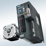
SINAMICS V90 basic servo drive system
SINAMICS V90 basic servo drive system The servo drive system comprises the basic SINAMICS V90 servo converter and SIMOTICS S-1FL6 servomotor. The system features eight converter frame sizes and seven motor shaft heights to cover a performance range from 0.05 kW to 7.0 kW for operation in single-phase and three-phase networks. The SINAMICS V90 servo drive system enables a wide range of simple Motion Control tasks to be implemented cost-efficiently and conveniently with the focus being on dynamic motion and processing. SINAMICS V90 servo drive system – an overview of its strengths Optimized servo performance Cost effective Easy to use Reliable operation Motor design optimized for the Asian market
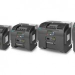
SINAMICS V20 basic inverters
SINAMICS V20 basic inverters SINAMICS V20 – Description Siemens is offering a simple and cost-effective drive solution with its compact SINAMICS V20 Basic Performance inverter. SINAMICS V20 sets itself apart as a result of its quick commissioning times, ease of operation, robustness and cost-efficiency. With five frame sizes, it covers a power range extending from 0.12 kW up to 30 kW. SINAMICS V20 – an overview of its strengths Easy to install Push-through and wall mounting – side-by-side possible for both USS and MODBUS RTU at terminals Integrated braking chopper from 7.5 kW to 30 kW (10 hp up to 40 hp) Easy to use Parameter loading without power supply Integrated application and connection macros Keep Running Mode for uninterrupted operation Wide voltage range, advanced cooling design and coated PCBs increase robustness Easy to save money ECO mode for V/f, V2/f Hibernation mode Optimized for solar panel powered pump system Overload capability for FSE (High – and Low Overload) SINAMICS V20 – an overview of the technology Voltage and power range: 1AC 200 V – 240 V, ±10 %; 3AC 380 V – 480 V +10 % / -15 % 0.12 kW – 30 kW (0.17 hp up to 40 hp) Control modes: V/f, V2/f, FCC SINAMICS V20 – typical applications SINAMICS V20 has a compact design, and can be individually adapted to the particular application or user requirements using various options (for example, an external BOP, connecting cable, filter, braking resistors, shielding, …). The compact and rugged devices are tailored for operating pumps, fans, compressors and conveyor belts as well as for basic drive applications in the process and manufacturing industries.
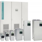
SINAMICS G180
SINAMICS G180 The LOHER DYNAVERT T frequency converter integrated as SINAMICS G180 into the SINAMICS range has been deployed for over forty years for applications where maximum reliability and availability of the drive are of paramount importance. SINAMICS G180 thus benefits from the many years of expertise acquired by LOHER Motors & Drives in the manufacture of motors and converters to the extent that the frequency converters are always systematically developed to take into account the requirements of the drive system as a whole. SINAMICS G180 converters can be supplied for standard voltages 400, 500 and 690 V in the output range up to 6.6 MW. They are available as a compact unit, a cabinet system or a cabinet unit, with air or liquid cooling, for operation with synchronous and induction motors. A wide range of add-on electrical components allow the drive system to be optimized for specific requirements. Configuring is greatly simplified by predefined interfaces and commissioning is speeded up by the preassignment of parameter settings at the factory. The accuracy of the sensorless vector control makes the converter an ideal partner for many types of drives, such as those used for pumps, fans, centrifuges, presses, extruders or compressors, and an additional actual speed value encoder is therefore superfluous. Appropriate encoder evaluation units are available for the SINAMICS G180 converters so that they can address applications that require an encoder for plant-specific reasons. The SINAMICS G180 can be flexibly integrated into any automation concept whether it employs a conventional control or a bus system. Apart from the standard converter interface (compliant with NAMUR NE37), the following can also be supplied as options to provide communication with the supervisory control system: PROFIBUS DP Modbus RTU Modbus TCP CANopen Ethernet (PROFIBUS DP with Ethernet-PROFIBUS converter) Optionally available peripheral boards can be selected to add the following inputs/outputs to the converter: Digital and analog inputs and outputs 2 PTC thermistor inputs for ATEX-certified motor temperature monitoring for motors in hazardous zones (prewarning/trip) Benefits The converters are exceptionally quiet and compact thanks to state-of-the-art IGBT power semiconductors and an innovative cooling concept. The clock frequency is optimized to reduce system losses to a minimum. The “random pattern” function significantly reduces motor noise. Plant and system availability are increased by being able to quickly and simply replace power components. Essential spare parts can be requested at any time for any individual converter by means of the “SparesOnWeb” Internet tool. Optimized use of components reduces cabinet dimensions to a minimum. Easy integration into automation solutions via analog and digital interfaces. Number of interfaces can also be expanded through installation of an optional peripheral board. Data are transmitted over popular bus systems (PROFIBUS DP, CANopen, Modbus RTU or Modbus TCP) Fast, easy commissioning and parameterization using interactive menus on an operator panel with illuminated graphic LCD and plain-text display, or PC-supported using the IMS commissioning tool (Inverter Management Software). The entire production process is required to meet stringent quality standards and subject to extensive controls, thereby ensuring a high degree of functional reliability during installation, commissioning and operation. Application The SINAMICS G180 is especially suited to applications in industries such as the chemical industry oil and gas industry power plant and utilities industries plastics industry process industry primary industry test bench systems conveyor systems and for general mechanical engineering applications. Design Platform concept All of the SINAMICS G180 versions are consistently based on an integrated, standardized, common, modular platform concept. Shared hardware and software components, as well as standardized tools for dimensioning, configuring and commissioning tasks ensure a high level of integration between all components. All devices – from the lowest rating class in compact unit form to the largest version in the form of an air-cooled or liquid-cooled cabinet unit – have the same features with a virtually identical scope of functions. All frequency converters in the SINAMICS G180 range operate with the Control Board. All Control Boards utilize the same firmware and all are operated via the Inverter Management Software IMS. Both the IMS and the firmware can be upgraded and downgraded as required to facilitate communication. Function Power unit Complies with EMC guidelines defined in EN 61800‑3 thanks to line filter which is integrated as standard (with grounded supply system) Category C2 for compact units in TN/TT system of the first environment (residential area), category C1 available as an option Category C3 for cabinet units (TN/TT system) of the second environment (industrial area) Category C4 for compact and cabinet units in IT system of the second environment (industrial area) SINAMICS G180 converters cause minor line harmonics: Thanks to line reactors integrated in cabinet units and DC reactors integrated in compact units Output filter to permit the use of long motor cables for motors with standard insulation Insulation monitoring for IT systems integrated in 500/690 V units and ground fault monitoring for TN and TT systems integrated in 400 V units Wide range of input voltages Lower additional motor noise emissions of typically 3 dB(A) as well as minor losses in converter and motor thanks to optimized pulse pattern and converter clock frequency Units can be protected by standard fuses (gL characteristic) Standardized user interface on units rated from 2.2 to 6 600 kW Control section High level of protection for personnel and plant is provided by protective separation of the safety extra-low voltage in accordance with IEC/EN 61800‑5‑1 at the analog and digital control inputs and outputs of the power unit. Operation and settings Straightforward to operate and set by means of a menu-assisted, 4-line plaintext display with membrane keyboard on the converter unit or remotely from the control room via an RS485 link at a distance of up to 1000 m Extensive range of functions using a Windows-based PC operating program Explosion protection ATEX-certified tripping concept in accordance with Directive 94/9 EC for the safe operation of motors in hazardous zones 1 and 2, which means that no main contactor is required Safe Torque Off Available with options G04, G05, G08 Shutdown mechanism to prevent unexpected starting. Category 0 stop function in accordance with EN 60204‑1 (stop by disconnection of power supply to the machine). Functional safety in accordance with: SIL 2 as per EN 61508 Category 3 to EN ISO 13849‑1 Performance Level (PL) d to EN ISO 13849‑1 Functional safety in accordance with IEC 61508: SIL 3 is possible in conjunction with options S01+Y11 or S02+Y11. Communication Communication via conventional terminal strip with freely programmable digital and analog inputs/outputs with parameterizable limit value signals parameterizable timers parameterizable attenuators parameterizable converter behavior when inputs/outputs respond parameterizable logic elements Communication and parameterization by means of PC using IMS (Inverter Management Software) via USB interface External operator panel via RS485 link Bus systems such as Ethernet (PROFIBUS with Ethernet-to-PROFIBUS converter board), PROFIBUS DP, CANopen, Modbus RTU or Modbus TCP Drive behavior Closed-loop control of synchronous and induction motors Two control modes for induction motors: Space vector control for standard applications (without feedback) Field-oriented closed-loop control for dynamic requirements Optimum braking without any supplementary equipment by means of oversaturation control system. With approximately 10 % braking torque at high speed range and up to 50 % at low to medium speed range. General Automatic slip compensation Stall protection provided by current limitation control Flying restart function for connection to rotating motor Automatic adjustment of the overload times Parameterizable DC braking for precise deceleration down to zero speed Torque control Automatic restart (Auto Restart) Voltage and current control systems (AC as well as DC with variable frequency) Mains supply backup is possible Integrated process controller for basic, higher-level closed-loop control tasks Optionally available integrated braking chopper for increased braking torque Operation of groups of units with interconnected DC links is possible
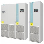
SINAMICS G150 Drive converter cabinet units
SINAMICS G150 Drive converter cabinet units SINAMICS G150 converter cabinet units, versions A and C With its SINAMICS G150 converter cabinet units, a drive system is available on which all line-side and motor-side components are integrated together with the Power Module extremely compact into a specially designed cabinet enclosure. This approach minimizes the effort and expense required to configure and install them. SINAMICS G150 has been specially designed to meet the requirements of drives with square-wave and constant load characteristics, with medium performance requirements, and without regenerative feedback capability. The control accuracy of the sensorless vector control is suitable for most applications, which means that an additional actual speed value encoder is not required. SINAMICS G150 converter cabinet units are optionally available with an encoder evaluation function in order to handle applications that require an encoder for plant-specific reasons. SINAMICS G150 converter cabinet units offer an economic drive solution that can be adapted to customer-specific requirements through a wide range of components and options. SINAMICS G150 is available in two versions: Version A All optionally available line connection components, such as the main switch, circuit breakers, line contactor, line fuses, line filter or motor-side components and additional monitoring devices, can be installed as required. This version is also available with power units connected in parallel. Version C Offers an extremely space-optimized structure without line-side components. This particularly slimline version can be used, for example, when line connection components are accommodated in a central low-voltage distribution panel (MCC) in the plant. Benefits Particularly quiet and compact converters thanks to state-of-the-art IGBT power semiconductors and an innovative cooling concept. Individual modules and power components can be replaced quickly and easily, which ensures a higher level of plant availability. Replaceable components have been designed so that they can be quickly and easily replaced. In addition, the “Spares On Web” Internet tool makes it easy to view the spare parts that are available for the particular order at all times. Can be easily integrated in automation solutions by means of a standard communications interface as well as a range of analog and digital interfaces. Easy commissioning and parameterization using interactive menus on the AOP30 Advanced Operator Panel with graphic LCD and plain-text display, or PC-supported using the STARTER commissioning tool (see Chapter Tools and configuration). Preset software functions make it easier to adapt the converter to the individual plant. For example, the key functions for controlling pumps are stored as a preprogrammed macro in the drive. With regard to EMC, the devices are subdivided into various zones, and as a consequence, they are extremely insensitive to disturbances and are very reliable in operation. With the help of simulated conditions, partitions have been designed to act as air guides and to help dissipate heat. Special measures used in the construction of the cabinets ensure that they remain mechanically durable over their entire life cycle. All components, from individual parts to the ready-to-connect cabinet, undergo rigorous testing throughout the entire production process. This guarantees a high level of functional reliability during installation and commissioning, as well as in operation. Application Variable-speed drives are ideal for all applications that involve moving, conveying, pumping or compressing solids, liquids or gases. Key applications include: Pumps and fans Compressors Extruders and mixers Mills
- GIẢI PHÁP SẠC XE Ô TÔ ĐIỆN NVCharge
- DANFOSS
- NĂNG LƯỢNG TÁI TẠO
- GIẢI PHÁP TÍCH HỢP
- Hệ thống biến tần trung, hạ áp
- Hệ thống cân băng tải
- Hệ thống chuyển nguồn điện tự động ATS
- Hệ thống điều khiển động cơ MCC
- Hệ thống điều khiển phân tán DCS
- Hệ thống điều khiển PLC - Scada
- Hệ thống điều khiển TPS
- Hệ thống giám sát và nhiệt trị than online
- Hệ thống khởi động mềm trung, hạ áp
- Hệ thống UPS
- Tủ điện phân phối MDB & DB, tủ cấp nguồn
- MARECHAL - TECHNOR
- BORRI
- FLENDER
- DURAG
- SOLCON
- SIEMENS
- METSO OUTOTEC
- DỊCH VỤ KỸ THUẬT
Liên hệ
CÔNG TY CỔ PHẦN THƯƠNG MẠI KỸ THUẬT HẢI ANH – HAI ANH JSC
Trụ sở tại TP Hà Nội:
+ Địa chỉ: P301, Nhà D5C, đường Trần Thái Tông, phường Cầu Giấy, TP. Hà Nội, Việt Nam
+ ĐT: (+84-24) 6269 7755
+ Fax: (+84-24) 6269 5556Trung tâm nghiên cứu, sản xuất công nghệ cao Nova Energy:
Lô đất CN1-12B – 1.3, Khu công nghiệp công nghệ cao 1, Khu Công nghệ cao Hòa Lạc, xã Hạ Bằng, Hà Nội, Việt Nam
+ ĐT: (+84-24) 3202 2677Chi nhánh tại miền Trung:
+ Địa chỉ: P1109, Toà A, chung cư Tecco Đông vệ, phường Hạc Thành, tỉnh Thanh Hoá, Việt Nam
+ ĐT: (+84-23) 7383 8886Chi nhánh tại miền Nam:
+ Địa chỉ: Tầng 1, Tòa nhà Gia Thy, 158 Đào Duy Anh, phường Đức Nhuận, Thành phố Hồ Chí Minh, Việt Nam
+ ĐT: (+84-28) 3517 8949
+ Fax: (+84-28) 3517 8950-

Hệ thống đo lường mạng ngoài – dự án Hòa Phát Dung Quất 2
-

Hệ thống tủ điện trung thế tại Xi măng Hoàng Mai
-

Hệ thống điện và điều khiển nhà máy HPS2 Phong Điền
-

Hệ thống điện trạm khí nén – Nhiệt điện Hòa Phát Dung Quất 1
-

Hải Anh JSC và VINALIFT ký kết hợp tác chiến lược cùng các đối tác công nghệ toàn cầu: Siemens, Innomotics, Flender

